
The air movement industry uses a common term to describe certain inlet and outlet conditions that adversely affect fan performance. The term used is “system effect.” Perhaps the term should be “fan installation effect” because system effect results from the difference in how the fan was tested, compared to how it is installed. To minimize system effects, air must enter or exit a fan uniformly.
First, let’s take a look at how fans are tested and cataloged. Most fans available in today’s market bear Air Movement and Control Association International, Inc. (AMCA) Certified Rating Seals. This means that the fan manufacturer followed the test procedures as outlined in AMCA Publication 210 and tested the fan in one of the standardized configurations approved by AMCA. One of the requirements of AMCA is that directly under the cataloged performance for a given fan model, the fan manufacturer must make a statement as to how that product was tested. Paying attention to these statements is the first step in avoiding system effect problems.
Typical statements for three different product types are:
Roof exhaust fans: Performance is shown for Installation Type A: Free inlet, free outlet. Power rating (BHP) does not include drive losses. Performance ratings do not include the effects of appurtenances in the airstream.
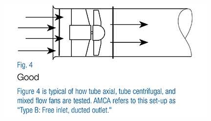
Tube axial fans: Performance is shown for Installation Type B: Free inlet, ducted outlet. Power rating (BHP) does not include drive losses. Performance ratings do not include the effects of appurtenances in the airstream.
Centrifugal fans: Performance is shown for Installation Type B: Free inlet, ducted outlet. Power rating (BHP) does not include drive losses. Performance ratings do not include the effects of appurtenances in the airstream.
It is important to realize that fan manufacturers only guarantee the fan to perform as tested. The following examples will show manufacturer test conditions compared to installation with obstructions, such as elbows, guards, or dampers, directly at the fan inlet or outlet. These obstructions cause additional losses that are not included in the fan manufacturer’s test, and in many cases, are not included in the designers’ usual system resistance calculations. Most designers are well-trained in determining the resistance that occurs in the system’s ducts such as filters, dampers, and elbows that are located some distance from the fan, but obstructions near the fan may be overlooked. The interaction of the air and the obstructions just prior to and immediately after the fan causes additional losses known as system effects. The following figures illustrate how fans are tested in comparison to how they are sometimes installed.
Roof Exhaust Fans
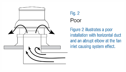
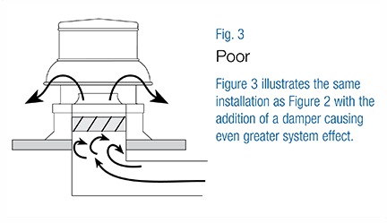
Figure 1 illustrates how roof exhausters are tested. Additional vertical straight duct would have little if any system effect. Figures 2 and 3 illustrate roof exhaust fan installations having system effects. Figure 3 illustrates the worst case because the damper is located in a turbulent airstream. To improve installations where horizontal ducts are used directly under the roof line, turning vanes should be installed in the elbows. In addition, a higher curb or extended base should be used. Higher curbs result in the inlet elbow being further from the damper and inlet fan.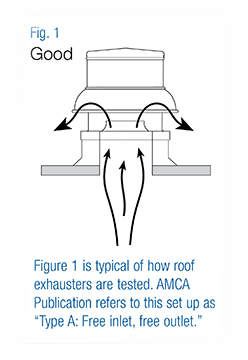
Tube Axial Fans
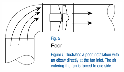
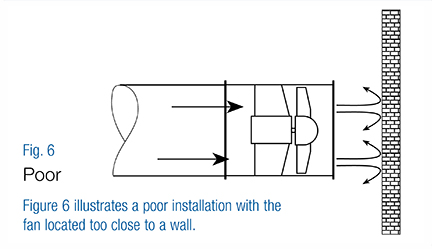
Figure 4 illustrates how tube axial, tube centrifugal, and mixed flow fans are tested. Illustrations with straight inlet ducts and inlet bells would result in similar performance. Without a discharge duct, a system effect will occur. (See Figure 12 below for recommended discharge.) Inline installations are subject to system effect both at the fan inlet and outlet, as shown in Figures 5 and 6. Figure 5 illustrates a poor inlet condition with an elbow directly at the fan inlet. Figure 6 illustrates a poor outlet condition where the fan discharges too close to a wall. Inline fans require the appropriate length of discharge duct in order to achieve cataloged performance. (Refer to Figure 12.)
Centrifugal Fans
Figure 7 illustrates how housed centrifugal fans are tested. Centrifugal fan installations are subject to the greatest possibilities of system effect due to the possibilities of both ducted inlets and outlets, plus multiple available arrangements, discharge positions, and CW or CCW rotations. Figure 8a illustrates a poor installation with an elbow directly at the fan discharge. This type of installation can be avoided by selecting a fan with the correct rotation and discharge position as shown in Figure 8b.
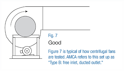
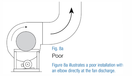
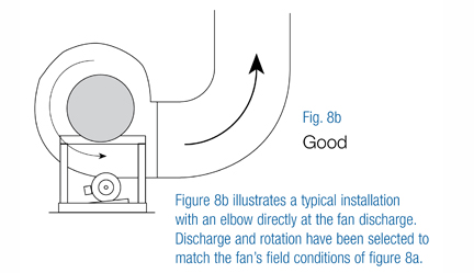
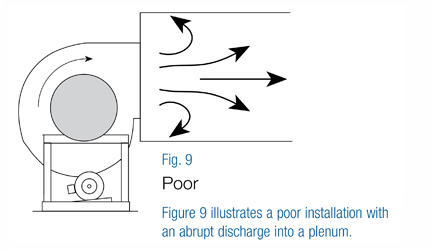
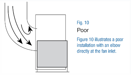
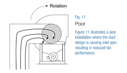
Figure 9 illustrates another poor installation with an abrupt discharge into a plenum. A system effect results if a given length of discharge duct is not present. (See Figure 12 for recommended discharge ductwork.) Both figures 10 and 11 illustrate installation with improper inlet conditions. Figure 10 could be improved with at least one fan wheel diameter of straight duct between the fan and the elbow. Installation as shown in Figure 11 should be avoided if possible because the effect of the inlet spin is difficult to define and correct.
The previous illustrations show only a few of the many installation possibilities that can cause system effect. Remember different types of fans are subject to different considerations based on how they were tested. AMCA Publication 210 shows four basic installation types. However, combining all fan types, fan arrangements, and the manufacturer’s choice of how to test, the installation possibilities are far too numerous to cover in this article.
What type of fans are affected by what condition and what condition presents the most common problems?
- Roof exhaust fans are affected by the inlet conditions.
- Roof supply fans are affected by outlet conditions.
- Fan types typically affected by both inlet and outlet conditions are inline fans (axial, centrifugal, and mixed flow) and housed single inlet centrifugal fans.
Fan installations with system effects should be avoided if possible. However, in many cases, space constraints or other factors prohibit designers from allowing for ideal conditions.
The following conditions (listed by inlet and outlet) cover the most common causes of system effect.
Causes of System Effect--Inlet Conditions:
- Elbows too close to the fan inlet
- Abrupt duct transition
- Inlet spin due to duct design
- Dampers not fully open
- Damper locations
- Poorly designed guards
- Inlet too close to walls or bulkhead
- Inlet boxes
Causes of System Effect--Outlet Conditions:
- Elbows too close to the fan outlet
- Abrupt transitions
- Free discharge
- Damper location
- Weatherhoods
- Discharge guards
- Discharge too close to the wall or bulkhead
How to Avoid Fan Installation Problems
The following recommendations will help in avoiding installation problems:
- Understand how the fan you selected was tested. (Refer to catalog statements under the fan manufacturer’s performance tables or fan curves.)
- For roof-mounted fans where the duct must run horizontally directly under the roof, install turning vanes in the elbow, plus consider using higher curbs or extended bases. This additional height will increase the distance from duct elbows and dampers in relation to the fan inlet.
- Consider different types of fans. For instance, if the duct must turn 90°, a housed single-width single inlet centrifugal fan installed in the turn could be a better choice than an inline fan with an abrupt duct elbow.
- Select housed centrifugal fans with the proper rotation and best discharge position for the situation.
- If an elbow is required at a fan inlet due to space constraints, use an inlet box that has a predicted loss in lieu of the elbow.
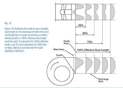
- Avoid free discharges for inline and centrifugal fans. Add the duct length required to obtain a uniform velocity profile and to minimize losses (see Figure 12).
It’s understandable that in many cases an installation will end up having an obstruction at the inlet or outlet (or both) causing system effect. If these situations cannot be avoided at the design stage, the system effect should be estimated and added to the calculated system resistance. Keep in mind that the standard procedures for the design of duct systems are all based on the assumptions of uniform flow profiles in the system. The standard adds for resistance of elbows and does not account for the loss when the elbow is close to the fan. AMCA has recognized this problem and has published guidelines on how to compensate for system effects in its Publication 201 “Fans and Systems.” The designers who fully understand system effects, and design to avoid them, must also follow up with the installers to make sure the installation is as planned.
What are the penalties of system effect? Even when we recognize the causes of system effect and we compensate for their losses, penalties result. The penalty starts with fans selected at higher speeds to compensate for additional losses. Higher speeds result in larger motors, increased cost, reduced efficiencies, increased vibration, and acoustical effects (sound noise). Acoustical effects are usually completely overlooked even though the acoustic system effect penalty might be quite severe. The severity depends on how inadequate the fan-to-system connection is. In any case, you cannot expect the fan sound ratings to be as cataloged if system effect exists.
Troubleshooting existing installations when the system is short of air and pressure due to overlooked system effects or poor installation practices can be quite challenging. In most of these cases, it’s very difficult to take accurate performance readings because of the obstruction and turbulence at the fan inlet and outlet.
When troubleshooting, a determination must be made whether it’s a system problem due to design and/or installation. Is the fan installed exactly as tested? In most cases, a visual inspection of the installation will lead you to a clear answer. To solve deficient fan system performance problems, it helps to have a clear understanding of fan and system curves plus a knowledge of how to apply the fan laws (see Figure 13).
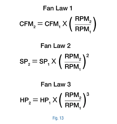
Figure 14 uses fan and system curves to illustrate the original design point, the deficient performance reading, and the new fan and system curve with system effect.
- Point 1 illustrates the original design point.
- Point 2 is the design volume on the corrected system curve.
- Point 3 is where the deficient volume falls on the original system curve.
- Point 4 is where the deficient volume falls on the corrected system curve.
(All of the above assumes that the air density and the fan’s speed are as designed).
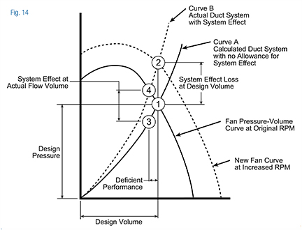
To further explain, let’s consider an example where the system is delivering 20% less air than design (Point 1). The deficient volume is point 3 as shown on the original system curve. The original curve calculation did not include allowance for system effect. The difference in point 3 to point 4 illustrates the system effect at actual flow volume. The difference from point 1 to point 2 illustrates the system effect at the desired volume (design volume). Because system effect is velocity related, the difference between points 1 and 2 is greater than the difference between points 3 and 4.
Points 2 and 4 fall on a new system curve. In order for the existing fan to produce the design volume (point 2) on the new system curve, the fan speed must be increased.
Here’s where the fan laws come into play. If 20% more air is required, the fan speed will need to be increased by 20%. The resulting static pressure will be 44% higher and the BHP will be 73% higher than the original values.
A new fan curve is developed as shown in Figure 14. The problem may not be over at this point. New fan drives and a larger motor may be required. Hopefully, the original fan can handle these new conditions. In some cases, it’s not possible to use the existing fan unless the installation can be modified to eliminate or reduce the causes of system effect.
Summary:
In summary, here are a few points to consider:
- At the design stage, don’t try to save a few dollars per square foot of space for proper fan installation. The cost of the resulting poor installation could be much greater.
- Carefully design the system so it can operate as intended. Personnel doing the installation and inspection should also be familiar with the causes of system effect.
- In correcting installations with system effect, changing the ductwork should not be the last consideration. Remember the penalties of system effect (energy consumption, operating cost, sound) will remain for the life of the project.
For a pdf of this application article, click here.
For more information on other topics, visit Greenheck’s online library where you’ll find a large assortment of informational pieces to help guide you through your next building project. We offer technical data, application articles, project profiles, videos, podcasts, industry articles, product literature, and more.


from